
An electrostatic powder coating gun does more than blow powder toward a workpiece. It transports the powder, charges its particles and releases them into the attraction field created by a grounded part. When an application problem occurs, the investigation must therefore include the feed system, compressed air, hooks, grounding, booth extraction and part geometry—not just the gun.
The working rule: read the part and the defect first, then change one parameter in small steps. Changing several settings at once hides which variable actually improved the result.
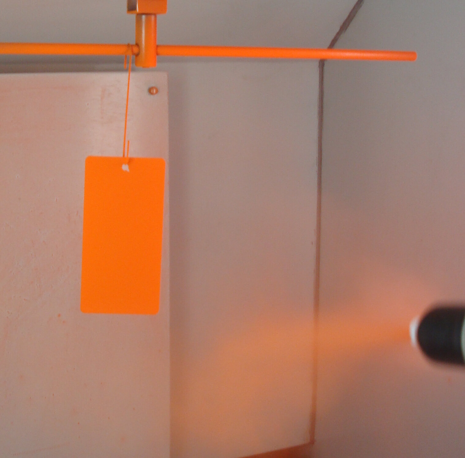
What do the five main gun settings control?
| Parameter | Primary function | Typical sign of poor adjustment |
|---|---|---|
| kV | Sets the electrical potential of the field between gun and part. | Excessive field can promote edge build and back ionization; too little can reduce transfer. |
| µA / current limit | Monitors or limits actual charge transfer to the part. It changes with distance and geometry. | Uncontrolled current can make recess penetration and recoating more difficult. |
| Powder output | Controls the mass of coating delivered to the gun over time. | Too much can create thick film, recovery load and an unstable cloud; too little slows coverage. |
| Flow / atomizing air | Moves powder through the hose and shapes the cloud. | High velocity can bounce powder off the part; low or unstable air can make the delivery pulse. |
| Distance and angle | Change the field, current, cloud width and particle velocity together. | Inconsistent distance produces striping, thickness variation and uneven appearance. |
No setting explains quality by itself. The same kV value can produce different current and deposition when the gun moves closer, hook contact improves or geometry changes. A production recipe should therefore record the part family, nozzle, distance, line speed and target film build together with the controller values.
A disciplined start-up sequence
- Verify safety and extraction. Do not spray unless booth extraction, filtration and safety interlocks are operating.
- Measure grounding. Clean metal contact must continue through the part, hook and conveyor; verify the acceptance limit against the equipment manual and applicable local rules.
- Condition the powder. Check storage conditions, fluidity and the fresh-to-reclaim ratio against the coating supplier's instructions.
- Select the nozzle. A broad panel, complex frame and narrow recess do not require the same spray pattern.
- Begin with the manufacturer's recipe. Use flat-part, recess, recoat or metallic presets as starting points, not universal values.
- Coat a test panel or representative part. Measure several locations and assess appearance and coverage together.
- Change one variable at a time. Adjust output, air and electrostatics in controlled steps and record the result.
How should kV and µA be read together?
kV represents electrical potential; µA represents the current flowing during application. Actual current usually changes as the operator changes gun-to-part distance. Current limiting and automatic feedback features are used to keep charging behavior under control as geometry changes.
A strong field can support transfer on a simple, bare part. Sharp edges, deep pockets, previously coated surfaces and an already thick powder layer can behave differently. In those cases, increasing voltage may make the problem worse. A suitable current limit, softer cloud, better angle and revised coating sequence are often more useful.
A high kV number on the display does not prove that more powder reaches the part. The result to verify is even film build, acceptable appearance and repeatable transfer.
How to coat Faraday areas
At inside corners, channels, box-section openings and deep recesses, electric field lines concentrate on outer edges. Powder builds there first and has difficulty reaching the bottom. This is known as the Faraday cage effect.
- Coat recesses before the exposed faces become heavily insulated by powder.
- Reduce powder output and transport velocity to create a softer cloud.
- Do not force the gun directly into the pocket; find an angle that lets the field and cloud enter.
- Use current limiting or the equipment's recess mode and verify it against the manual.
- If outer edges build rapidly, reconsider field strength and sequence instead of simply spraying longer.
Small craters, star-like marks or sudden roughness can indicate back ionization. Likely contributors include excessive film build, excessive charge, insufficient gun distance or poor grounding.
Corona and Tribo guns
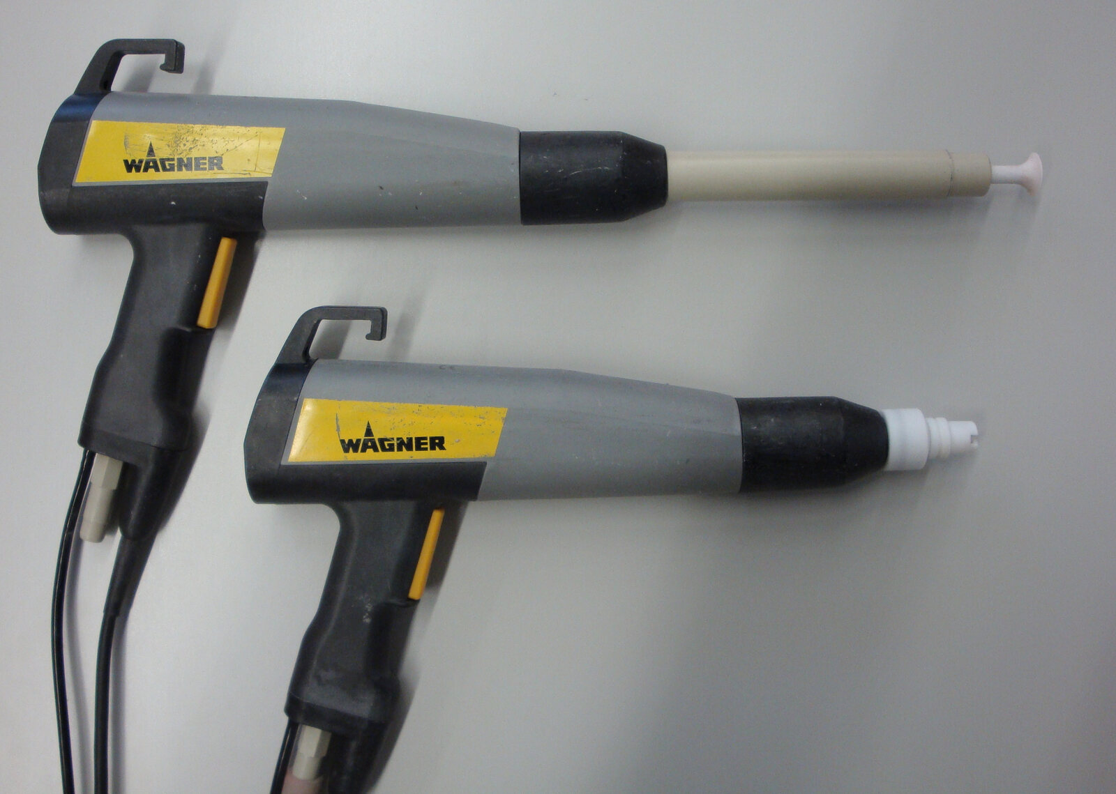
Corona systems use a high-voltage electrode at the gun tip to charge the powder through ionization; kV and current control are common. Tribo systems charge particles through friction against a suitable material inside the gun. Their behavior can be more sensitive to powder formulation and conditions such as humidity. Not every powder is equally suitable for Tribo charging, so compatibility must be confirmed with the coating and equipment suppliers.
Why nozzle selection matters
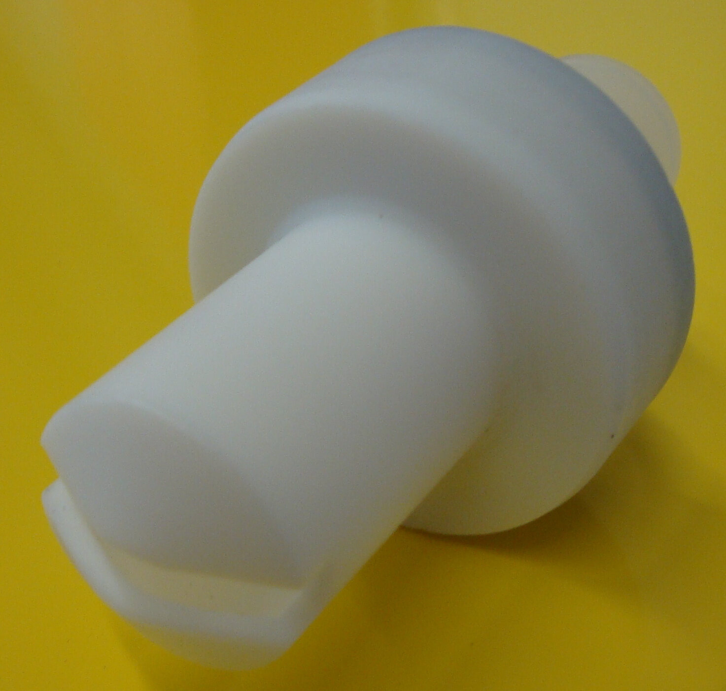
The nozzle changes not only cloud shape, but also particle velocity and how powder arrives at the surface. Flat-spray nozzles can provide a broad, controlled pattern; round or deflector patterns may suit pipes, frames and complex parts. Extensions and recess nozzles should only be used when approved for the specific equipment.
As a nozzle wears, the pattern may distort, spray may drift to one side or impact-fused powder may accumulate inside. Adding more air to compensate for a worn part is not a stable correction.
Manual gun technique
- Keep the gun as perpendicular as practical on broad faces and maintain a consistent distance.
- Standardize pass speed and overlap using measured film build rather than appearance alone.
- Do not dwell in one location; edges and corners can build film quickly.
- Coat difficult areas first, then finish the broad visible faces.
- Avoid abrupt movements that disturb booth airflow and the powder cloud.
- For colour change, follow a written sequence for the hose, pump, gun path, nozzle and booth.
Quick symptom-to-action guide
| Symptom | Check first | Next action |
|---|---|---|
| Recess bottom will not cover | Grounding, edge build, output and air velocity | Coat the recess first; soften the cloud and optimize angle and current control. |
| Powder bounces from the part | Flow/atomizing air, distance and booth air balance | Reduce particle velocity and correct pulsing in the hose or nozzle. |
| Crater-like roughness | Film build, charge, distance and grounding | If back ionization is suspected, reduce field and build; test one change at a time. |
| Pulsing delivery | Powder level, fluidization, injector/pump and hose bends | Clean the powder path to the manufacturer's procedure and inspect wear parts. |
| One side is consistently heavy | Nozzle wear, gun angle, part swing and operator pass | Inspect the nozzle and re-establish the distance and movement standard. |
| Recoat will not accept powder | First-coat thickness, grounding and electrostatic recipe | Use the recoat mode/current limit and try a softer application. |
Start-of-shift and end-of-shift checks
Cleaning and safety rules that cannot be compromised
Powder coating can form a combustible airborne dust cloud, while the electrostatic system operates at high voltage. Booth extraction and filtration must run, conductive equipment and parts must be properly grounded, ignition sources must be controlled and operators must use protection defined by the coating safety data sheet and the site's risk assessment.
- Before servicing a nozzle or electrode, switch off electrostatic power, discharge the system safely and apply the site's energy-isolation procedure.
- Do not immerse the gun in solvent; use only cleaning methods and materials approved by the equipment manufacturer.
- If compressed-air cleaning is permitted, use low pressure with booth extraction operating; do not spread powder into the work area.
- Do not substitute conductive O-rings, hoses or safety components with arbitrary parts.
- Do not rely on visual inspection for grounding; verify it with suitable test equipment at a documented interval.
CONCLUSION
A good gun recipe is a recorded balance.
A repeatable recipe contains more than kV and µA. Powder output, air, nozzle, distance, angle, coating sequence, grounding and target film build belong in the same record. That makes the result reproducible even when operators change.
Ferovant evaluates gun settings together with the powder, part geometry and line conditions to help separate the actual causes of application problems.
Let us review your application